Electrode Placement and Lead Selection
Proper electrode placement is essential to acquire an accurate ECG record. ECG monitor manufacturers provide safe use instructions that will include electrode placement guidelines specific to their products. Always adhere to your facility policy and procedure when administering any patient care.
The following are some general guidelines when performing an ECG:
- Check the physician order or protocol
- Wash hands when entering patient room and before touching patient
- Identify yourself to the patient and describe the purpose of your presence
- Identify the patient (per policy)
- Describe the procedure: positioning, skin prep, electrode placement and characteristics, also the need for stillness during recording.
- Encourage the patient to ask questions
- Provide privacy
- Check the equipment, electrical supply, cables (intact, secure and correct connections)
- Attach skin electrodes to cables or contacts
- Choose sites that minimize interference from adipose, muscle movement, bony prominences, avoid non-intact skin
- Skin preparation:
- Remove excess hair from electrode site (electric clippers are preferred over shaving due to abrasion injury associated razor use).
- Inspect the site, skin should be intact, clean, dry, smooth and flat.
- Prepare each site with a clean dry gauze pad to remove excess skin oils, skin cells and residue. If skin is excessively oily use soap and water, dry thoroughly. Avoid using alcohol as it can dry the skin and increase impedance.
- Inspect and place electrode. Rub the electrode to ensure proper contact.
- Electrodes should be changed as needed and every 24/36 hours
- Verify that the monitor is detecting each beat, compare patient pulse to monitor display
- Set upper and lower limits per policy
- Run a strip, verify correct patient identification and data are recorded per policy
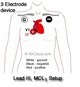
 3 Electrode Monitoring systems are common in acute care when continuous monitoring is indicated. They are used to track heart rate, detecting R waves for synchronized cardioversion, and detecting ventricular fibrillation, brady and tachyarrhythmias. The three electrode devices are inadequate for sophisticated diagnosing and monitoring, e.g. bundle branch blocks, wide QRS and ischemic ST segment monitoring.
Bipolar limb leads
I, II and III
Each bipolar leads has a positive (+) and (-) electrode. Bipolar leads can provide information about the direction and amplitude of a depolarization wave as it propagates through the myocardium.
- A depolarization wave moving toward a (+) electrode produces positive upward deflection on the ECG tracing.
- A wave with a net current movement toward a (-) electrode produces a downward deflection (negative).
- A wave moving perpendicular to the (+) and (-) electrodes will be neutral or flat.
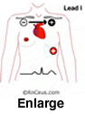 Lead I compares the flow of current between the right arm electrode (-) and the left arm electrode (+). Lead I offers a lateral view of the left ventricle and left atrium.
- Lead II views the left and right ventricles from the apex. It is the most commonly monitored
lead, producing the universally recognized normal sinus rhythm (NSR) tracing. In a healthy heart, the following electrical activity is depicted in the Lead II NSR tracing
 Atrial depolarization begins in the sinus node and moves toward the (+) electrode producing the first upright deflection, the P wave.
- Q wave is the first negative deflection below the isoelectric line in the NSR tracing. It is produced as the depolarization wave enters the septum. Upon entering the septum, current flows to the right ventricle at an angle greater than 90o from the (+) electrode which produces the negative deflection.
- R wave amplitude is explained by the nearly instantaneous depolarization of the majority of myocardium. Depolarization is directional from the myocardium toward epicardium and the (+) lead.
- S wave negative deflection represents late phase depolarization of residual myocardium and a small current flow away from the (+) lead.
 T-wave in Lead II should have a positive deflection. This is because the repolarization process, primarily characterized by the outflow of potassium ions (K+), generates an electrical current that begins in the epicardium at the base of the heart and advances towards the cardiac apex, moving toward the positive electrode of Lead II.
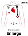
- Lead III provides a view of the right and left ventricles. Lead III along with leads I, II and the unipolar leads aVR, aVL and aVF can be helpful when determining cardiac axis.
- MCL1 using a 3 electrode device can capture electrical activity similar to but not exactly the same as the V1 lead displayed on a five or twelve electrode machine. MCL1 may be particularly useful for detecting arrhythmias that originate from the right ventricle or right atrium.
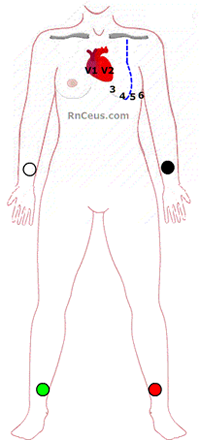
- MCL6 using a 3 electrode device can be used when electrodes cannot be placed on the sternal border to capture electrical activity from the left ventricle and to a lesser degree the left atrium. Electrodes are place:
- Positive Electrode (LA): The LA electrode is placed in the V6 position
- Negative Electrode (RA): The RA electrode, placed on the right arm or right side of the chest
- Ground Electrode (LL): The LL electrode, placed on the left leg or lower torso.
MCL1 and MCL6 can be useful in various clinical scenarios where quick and focused cardiac monitoring is necessary. The 12-lead ECG provides the best views of
electro cardiac activity including the differentiation of supraventricular tachycardia and ventricular tachycardia, but when time, resources or extended inpatient monitoring require, the MCL1 and MCL6 leads can provide valuable information.
V1-V6 leads can be viewed with a
five lead system by moving the center lead to the V1 or V6 position. Positive Electrode (LA): The LA electrode is placed in the V6 position, which will act as the positive electrode in this configuration.
|
|
 |
| Selecting ECG lead configuration based on patient condition |
|
Clinical concern |
Lead
|
| Bundle branch block (RBBB) |
• Leads: V1 and V2 (to observe the characteristic "rsR'" or "M" pattern
• Leads: I and V6 (to observe the broad, slurred S wave)
|
| Left Bundle branch block (LBBB) |
• Leads: V5 and V6 (to observe the broad, notched R waves, often described as a "W" pattern)
• Leads: I and aVL (to observe the broad, notched R waves)
• Lead: V1 (to observe the deep, broad S wave) |
|
Anterior
ischemia |
Leads: V3 , V4
|
|
Septal
ischemia |
Leads: V1 , V2
|
|
Lateral
ischemia |
Leads: I, aVL , V5 , V6
|
|
Inferior
ischemia |
Leads: II, III, aVF
|
|
Right ventricle
ischemia |
Leads V4R
(right-sided lead) |
|
Junctional rhythm with retrograde P waves |
Leads: II, III, and aVF (to visualize retrograde P waves) |
|
Optimal view of atrial activity
|
Leads: V1 (best for P wave visualization)
|
|
Ventricular ectopy, wide complex tachycardia |
Leads: V1 and V6 (to assess the morphology of the wide complex) |
|
Ventricular pacing
|
Leads: V1 and V6 (to verify pacing spikes and capture) |
Trouble shooting and tips
- Change the electrodes everyday.
- Make sure all electrical patient care equipment is grounded.
- Be sure all the lead cables are intact. Some manufacturers
require changing the cables periodically.
- Be sure the patient's skin is clean and dry.
- Make sure the leads are connected tightly to the electrodes.
- Patient movement frequently causes interference. For example,
the action of brushing teeth may cause interference that mimics V-tach.
References:
Paul, A., & Jacob, J. R. (2023). Electrocardiographic lead reversals. Indian pacing and electrophysiology journal, 23(6), 205–213. https://doi.org/10.1016/j.ipej.2023.09.005
Shue McGuffin, K., & Ortiz, S. (2019). Daily Electrocardiogram Electrode Change and the Effect on Frequency of Nuisance Alarms. Dimensions of critical care nursing : DCCN, 38(4), 187–191. https://doi.org/10.1097/DCC.0000000000000362
©RnCeus.com